© 2025 All Rights Reserved
Av. Perfecto Palacio de la Fuente, 6
03003 Alicante, España
E-mail: info@karkasys.com
Tel: +34 67070253
Contact us


System mounting joints KARKASYS
Mounting nodes VU-CONNECT, HOOK-BRACKET и TELEBRACKET — are integrated technical solutions for installing facade panels, window units and load-bearing elements of the system KARKASYS in various types of building structural schemes.
Each solution is designed considering:
• elimination of welding and wet processes,
• fast and precise installation,
• thermal continuity,
• concealed installation inside panels or frame.
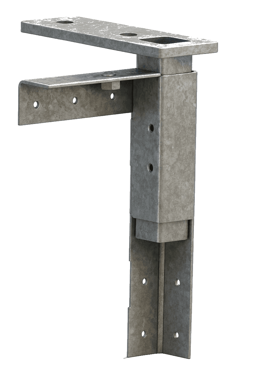
Adjustable bracket
assembled
Mechanism
adjustment
Bracket
reinforcer
panels
Horizontal panel joint
Floor slab bracket
Vertical panel joint
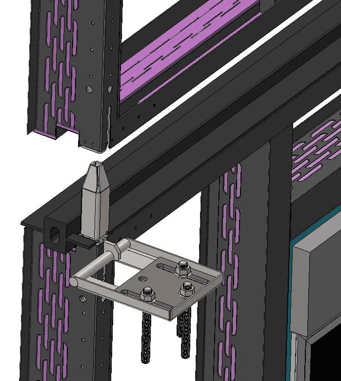
HOOK-BRACKET
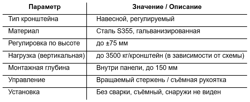
Adjustable mounting bracket for curtain panels
HOOK-BRACKET — is a removable mounting bracket with a hook-shaped lock and built-in vertical adjustment mechanism. Designed for installing facade panels PanelKIT, PanelCORE and other modules KARKASYS in buildings with reinforced concrete frame.
Purpose and scope
• Used for hinged installation of panels on the floor slab edge;
• Provides reliable and adjustable fastening to the support plate fixed on the reinforced concrete floor slab;
• Installed in factory mounting nodes at the corners of the panel (inside the thermal beam ThermoBEAM);
• Compatible with any floor slab (with concrete, metal or wooden surface with anchor fixation].
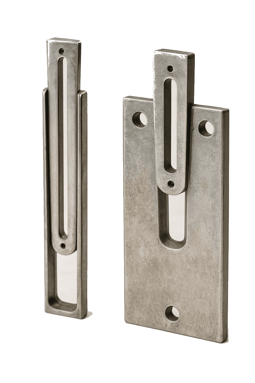
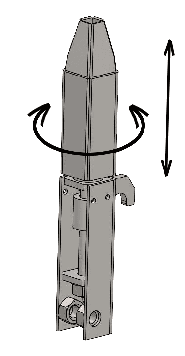
Construction and operating principle
• The main element is a metal hook, hung from top to bottom on a support plate previously fixed with anchors in the floor slab;
• The hook is connected to a movable vertical screw transmission, allowing precise height adjustment of the panel;
• Rotation is performed using a rotary handle included in the kit (or a removable rod];
• After hanging and adjustment, the panel automatically takes the design position without additional fasteners;
• The bracket works in shear and pullout, bearing the main vertical load of the panel.
Mounting scheme
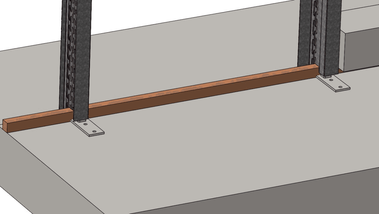
1. Installation of the support plate on the floor slab (with anchors];
2. Simple integration HOOK-BRACKET into the panel (into the corner mounting socket];
3. Hanging the panel from top to bottom with precise engagement of the hook on the support plate;
4. Height adjustment using a screw;
5. Fixing the position and continuing installation of adjacent panels.
Bottom mounting
structural elements
Telescopic bracket assembly
Corner
reinforcement bracket
panels
Movable part
bracket
Top mounting
structural elements
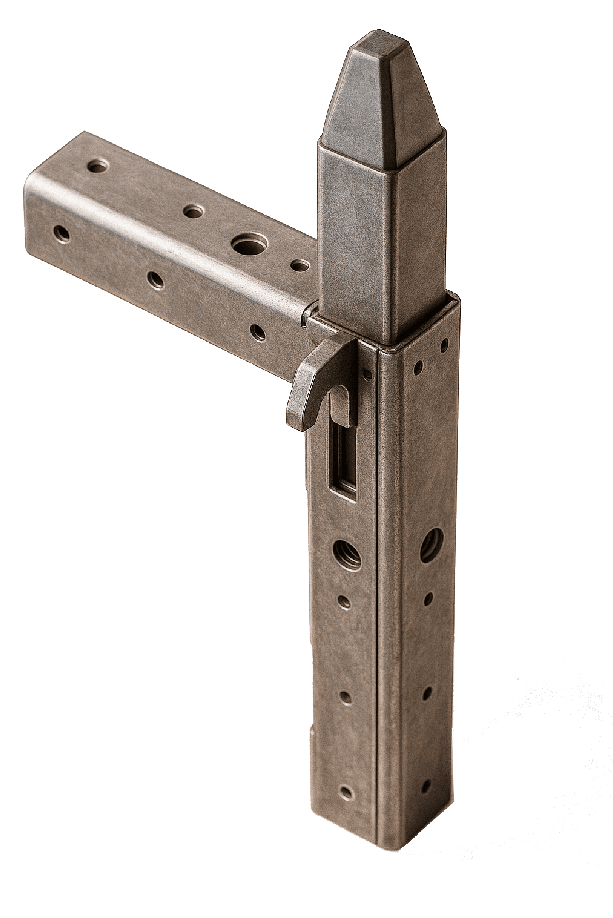
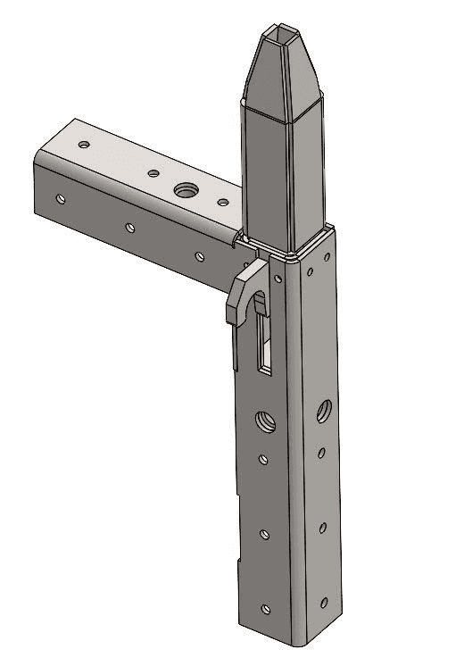
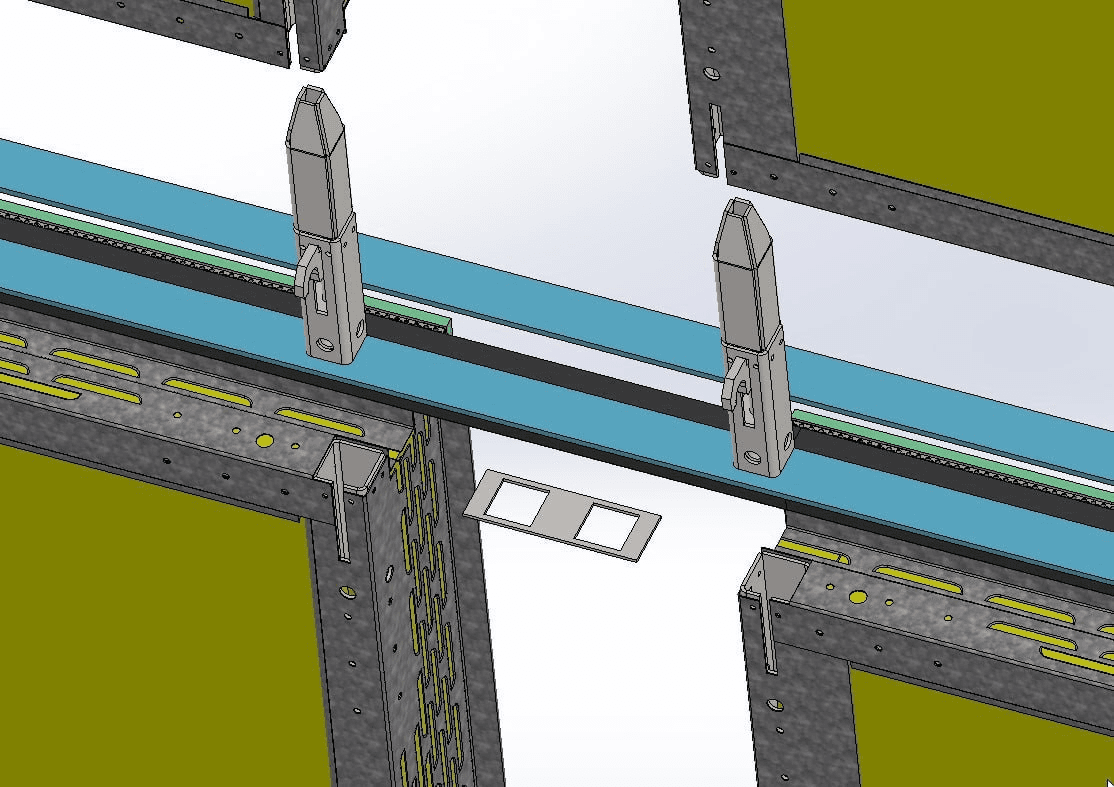
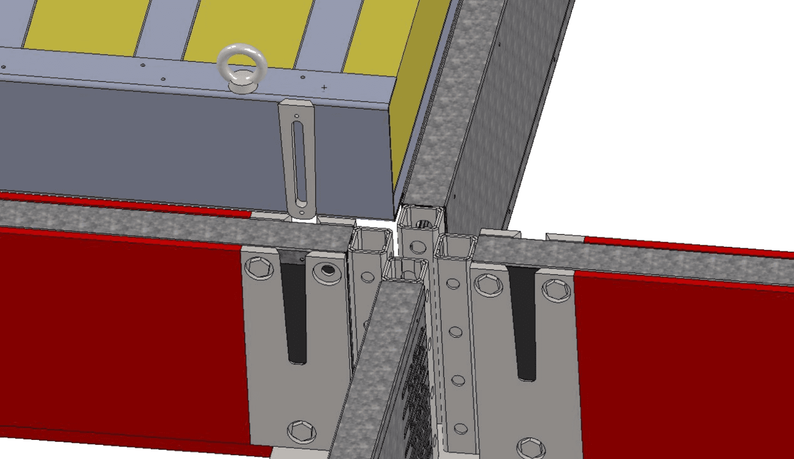
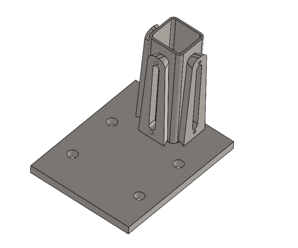
TELEBRACKET
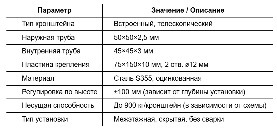
Telescopic mounting bracket for panel attachment between floors
TELEBRACKET — is a built-in telescopic bracket providing attachment of facade panels or pre-frames between floor slabs when installed in a reinforced concrete frame. The design allows vertical adjustment and reliable fixation of the panel in place without the use of welding and wet processes.
Purpose and scope
• Used for embedding panels and window units (pre-frames] into the space between floors (inter-floor installation];
• Provides adjustable support and fixation panel or pre-frame in design position;
• Installed into the factory node at the panel end, with concealed installation capability;
• Designed for use in systems PanelKIT, PanelCORE, ThermoFRAME, when a reinforced concrete building frame is used.
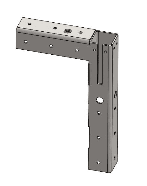
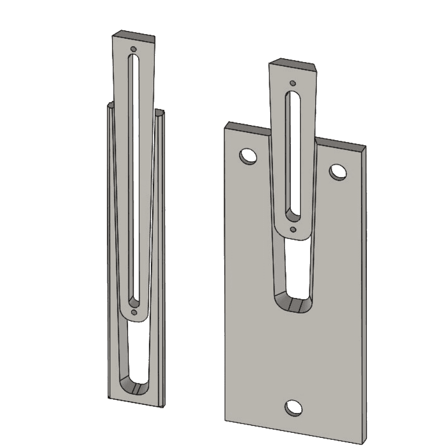
Construction and operating principle
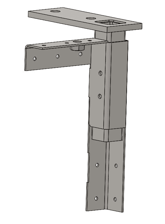
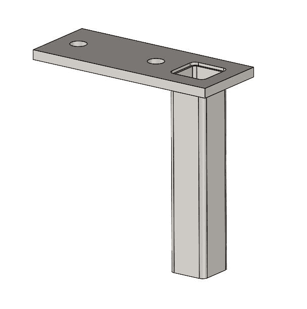
• The bracket consists of two square tubes:
• External — 50×50×2.5 mm
• Internal movable — 45×45×3 mm
• Into the inner tube in the upper part is welded mounting plate (thickness 10 mm, width 75 mm, length 150 mm] with two holes ⌀12 mm, offset 35 mm from edges;
• After installing the panel in place, the installer smoothly raises or lowers the internal element, achieving precise positioning;
• Then the plate is attached to the bottom side of the upper floor (or to the upper guide] using anchor bolts.
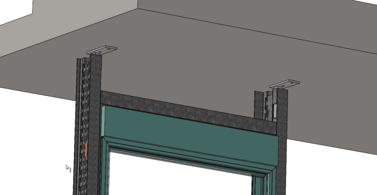
Mounting scheme
1. Factory installation TELEBRACKET into the panel or pre-frame edge;
2. Lifting the panel to a position between floor slabs;
3. Height adjustment — until reaching the design mark;
4. Anchor fastening of the mounting plate to the floor slab from above;
5. Completion of installation and installation of the next panel / pre-frame.
Beam - corner post assembly
on upper levels
Installation scheme
floor slabs
VU-connector
VU-CONNECT benefits:
• Hidden mounting — no visible nodes on the facade or in the interior.
• No welding or wet processes — ideal for industrialized assembly.
• Increased precision — geometric fixation eliminates distortions.
• site.features.quick_install — assembly in seconds without tools.
• Detachable node — suitable for temporary structures and reuse.
Support bracket (heel]
Beam - post assembly
on support bracket
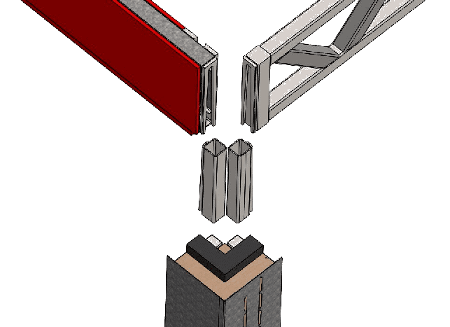
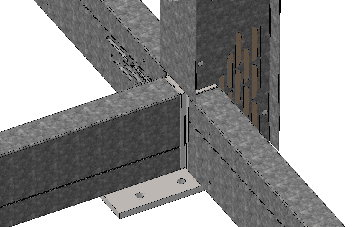
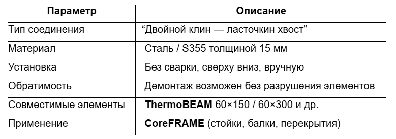
VU-CONNECT
Hidden "double wedge - dovetail" connection.
Key mounting element of the system KARKASYS. Provides fast and reliable connection of thermal profiles ThermoBEAM in the frame without using welding, bolts or wet processes.
Operating principle
• Consists of two connecting parts:
• Lower element (receiving part] — fixed inside the post or beam of the lower level.
• The upper element (insert wedge] — enters the groove from bottom to top under its own weight or with light force.
• Geometry double wedge with dovetail profile provides:
• Automatic centering during assembly,
• Protection against displacements and play,
• Increased connection strength.
Technical specifications
Technical specifications
Documentation and images:
• Technical drawing HOOK-BRACKET (DXF / PDF)
• Installation instructions with step-by-step diagram
• Illustrations of application in facade nodes
• Photographs and renders from the factory / construction site
Compatibility and integration
• Building frame: reinforced concrete, hybrid
• Allows combination with pre-frames ThermoFRAME
• Installed without changing the facade geometry — completely inside the panel
• Can be combined with lower guides or other horizontal fasteners if required
Compatibility and integration
Applicable to:
• PanelKIT, PanelCORE, ThermoFRAME
• Pre-frames designed for placement in inter-floor space
Compatible with:
• Concrete, wooden and metal floor slabs
• Insulated pre-frames and engineering inlet systems
• Installed without protruding elements — completely within the panel dimensions
Construction features
Documentation and images:
• Assembly drawing TELEBRACKET (PDF / CAD)
• Node schemes for installation in reinforced concrete frame
• Photographs of samples and CAD renders
• Installation instructions